


Your mixers are running, but are they running at the right speed? In many mixing applications, speed directly affects batch quality and consistency, yet it often goes unmonitored. In this article by Atlas Copco, you will discover that even if retrofitting existing equipment can seem costly or complex, adding speed measurement can be surprisingly straightforward and deliver immediate process improvements.
Content provided by Artur Marksted & Damien Feller, Lab engineer and product manager at Atlas Copco
Why speed matters
Most mixers run blind. Your motor turns, the impeller spins, and you assume the speed stays constant.
That assumption is a risk.
Many mixers operate without any feedback on actual shaft speed. While the motor may be supplied with constant voltage or air pressure, the load rarely remains constant. Changes in liquid level, viscosity, or temperature all affect motor speed.
Without measurement, RPM variations remain invisible, leading to inconsistent batches and reduced process reliability. By monitoring speed, operators can detect drift, verify performance, and build a more repeatable mixing process.
Measuring RPM with pulse signals
The simplest way to measure rotational speed is with a pulse signal. A sensor detects a repeating feature—such as a gear tooth or metal target—on the rotating shaft and generates one pulse each time it passes. The number of pulses produced during one full revolution is known as the Pulses Per Revolution (PPR).
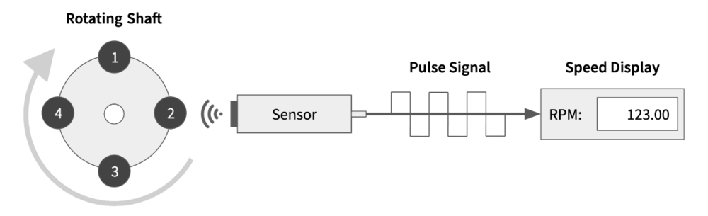
The sensor measures the pulse frequency (Hz), which is then converted into RPM using:
RPM = (Frequency × 60) / PPR
For example, if the sensor measures 20 Hz with a PPR of 4, the shaft speed is 300 RPM. Higher pulse frequencies indicate higher rotational speeds, while a higher PPR provides finer measurement resolution for applications requiring fast, accurate feedback.
Choosing the right sensor
Two sensor technologies are commonly used:
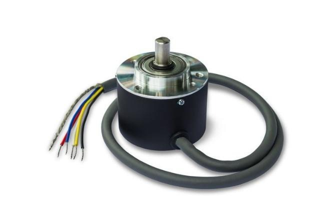
- Incremental encoders provide very high resolution and can detect rotation direction. However, they require shaft access, precise alignment, mounting brackets, and additional installation space.
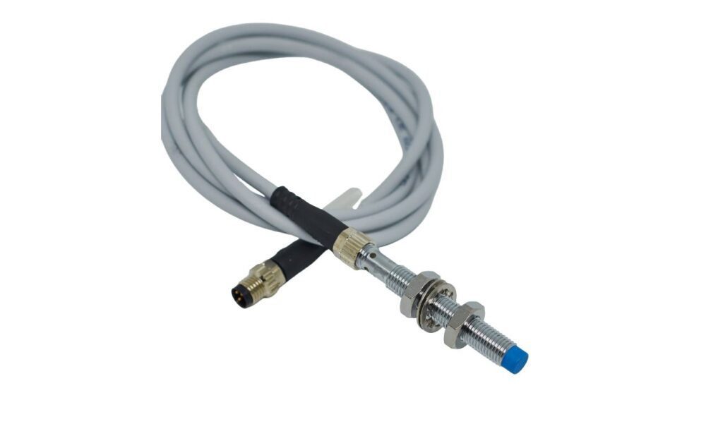
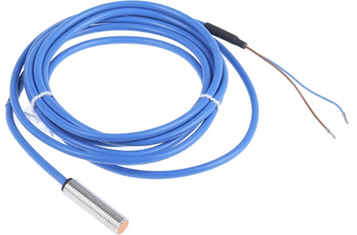
- Inductive proximity sensors detect passing metal targets without physical contact. They are compact, robust, resistant to vibration and contamination, and require minimal installation effort.
For most industrial mixing applications, inductive sensors are the preferred solution. They are easier to install, simpler to clean in washdown environments, well suited for ATEX applications, and provide more than enough accuracy for speed monitoring. The main specification to verify is the sensor’s switching frequency, which must exceed the maximum pulse frequency generated by the application.
| Feature | Rotary Encoder | Inductive Sensor |
|---|---|---|
| Installation | Complex. Needs a coupling and a bracket. | Easy. Points directly at the shaft or gear. |
| Precision | Ultra-high. Best for exact positioning. | High. Perfect for steady speed monitoring. |
| Durability | Sensitive to dust and vibration. | Tough. Handles oil, water, and heat. |
| Cost | High | Almost nothing |
| Washdown / Hygiene | Difficult | Simple |
| Direction Feedback | Yes | No |
Turning measurements into useful information
Once the pulse signal is available, it can be displayed in several ways.
For simple installations, a digital tachometer provides an instant RPM readout with virtually no programming. In automated systems, the signal can be connected directly to a PLC high-speed input, allowing the HMI to display live RPM values, historical trends, and alarm conditions.
More importantly, the speed signal becomes valuable process data that enables:
- Real-time RPM monitoring
- Batch verification
- Operating hour tracking for maintenance planning
- Early detection of abnormal operating conditions
- Closed-loop speed control for automatic regulation
Instead of simply knowing the motor is running, operators know it is running at the correct speed.
A practical example
The easiest installations are those where speed measurement is already built into the motor design.
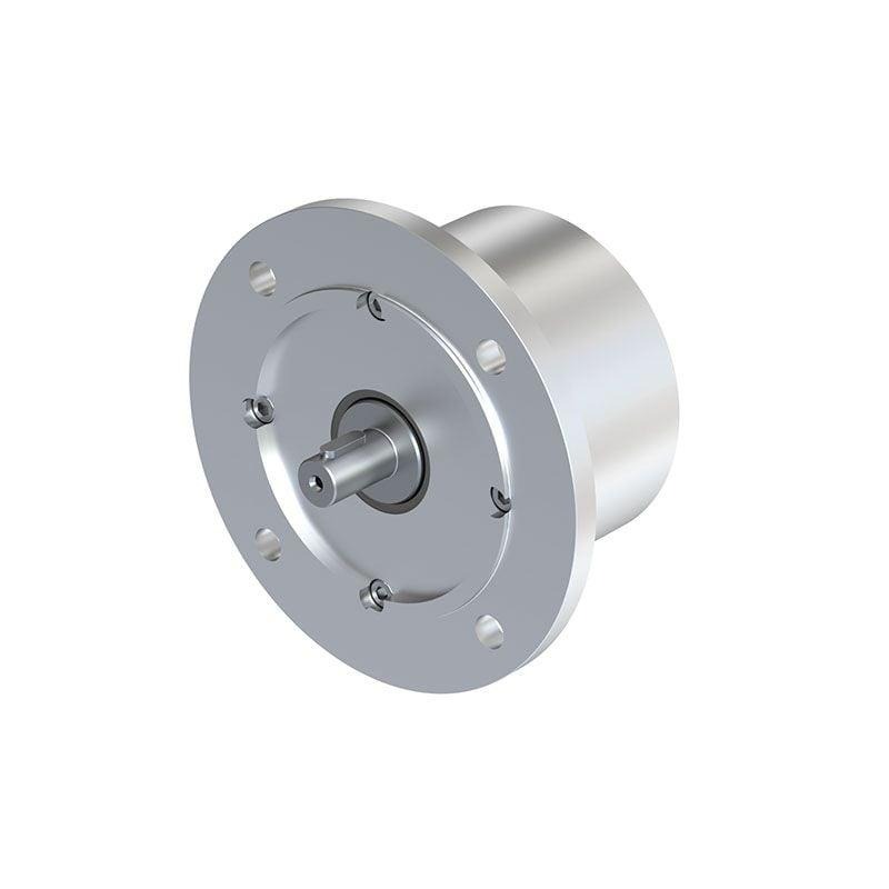
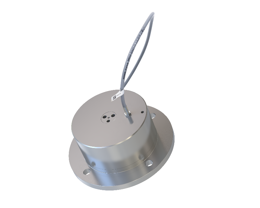
The Atlas Copco PZB piston air motor includes an integrated port for an M5×0.5 inductive sensor. Retrofitting requires only three steps: remove the sealing screw, install a standard M5 inductive sensor, and connect the cable.
The sensor sits flush with the motor housing, with no exposed bracket, no shaft coupling, and no alignment to manage. From a hygiene and installation standpoint, there is nothing to catch contamination and nothing to knock out of position during cleaning.
For applications where speed measurement is a must, but space or mechanical complexity is a constraint, this is the most direct path from no measurement to a working RPM signal.
For more information, contact Atlas Copco here.